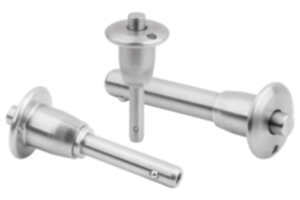
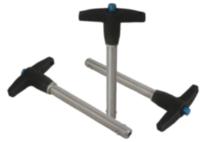
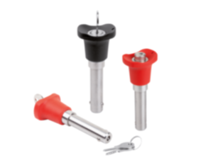
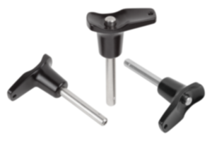
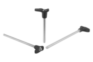
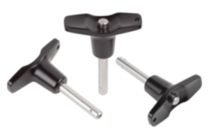
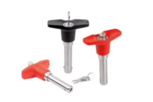
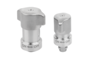
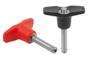
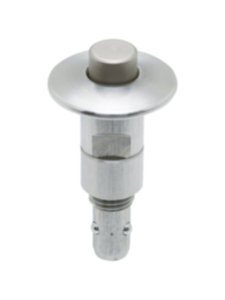
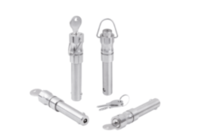
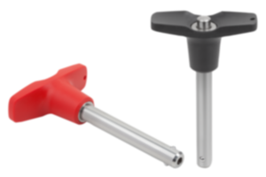
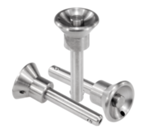
Ball lock pin stainless steel 03415-102116120
- Pour un assemblage simple et rapide d'éléments de machine et de pièces
- Domaines d'application : construction de machines, fabrication d'appareils, construction de dispositifs, technique de mesure, ménages
- Verrouillage sûr en appuyant et en relâchant simplement le bouton pression
- Autobloquant
- Résistance élevée au cisaillement
Sales unit
€56.47
plus sales tax
Registered customers are offered live availability of the item after logging in to the website. Please log in or register to see the live availability or request a quotation.
Added to your shopping cart
Designation
Ball lock pin
Form
B
Form definition
with recess. grip a. ring
Main
material
stainless steel
Component
material
stainless steel
D1=Pin diameter
16
L=Length
120
D
22
D2
19
D3
20
D4
33
L1
13,1
L2
39,5
L3
59,3
L4
30,3
L5
133,1
Receiving
hole
H11
16
SW
21
Shearing force
double shear
max.kN
153
ball lock pin
grip
Ringgriff Riffelung mit Bügel
~ CONFLICT MINERALS 3TG status
no intentional 3TG
~ CP65 substance 2 cancer
nickel (metallic)
~ PFAS free?
yes
~ REACH SVHC-free?
yes
~ RoHS conformity
yes, without exemption
~ TSCA 6(H) conformity
yes
Description
Matière
Poignée et bouton pression en inox 1.4305.
Goupille en inox 1.4305.
Billes en inox 1.4125.
Ressort de pression et anneau en inox 1.4310.
Finition
Bright.
Note
Ball lock pins are used for easy fastening or joining of components.
The two balls are disengaged by pressing the push button and the pin can be slipped into holes in the workpieces. When the push button is released, the balls lock the connection securely.
Shear force double shear (F) = S · τ aB max.
The values given for the shear force are the theoretical breaking load.
These are non-binding reference values without consideration of safety factors and exclude any liability. The values given are for information purposes only and do not constitute a legally binding assurance of properties.
The load values have been calculated in accordance with DIN 50141. Each user must determine individually whether the ball lock pin is suitable for the respective application.
Different materials in which the ball lock pins are used, weather conditions and wear can influence the determined values.
Accessory
Locating bushes for ball lock pins K0724
Safety spiral cable K0367
Retaining cable with loop K0367
Key ring K0367
Safety spiral cable K0367
Retaining cable with loop K0367
Key ring K0367
Important note on downloading CAD models
In order to download our CAD models, you must log in first. If you have not created an account yet, please register under "My Account" (right side of the screen) and follow the instructions.
D'autres clients ont également acheté