{"product":{"productId":"agid.27646","price":349.29,"name":"VÉRIN DE BRIDAGE À LEVIER PNEUMATIQUEDOUBLE EFFET, DK=25, CANAUX FORÉSALUMINIUM"},"currency":"EUR"}
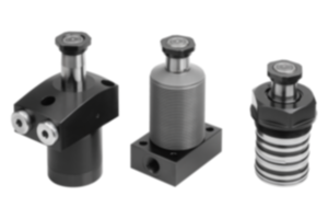
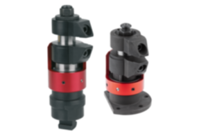
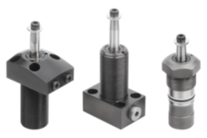
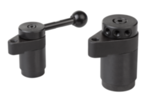
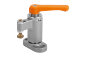
rotary lever clamp
pneumatic
aluminium
- Absence de forces transversales lors du serrage
- Faible encombrement
- Choix varié de poignées indexables
- Accès sans collision à la pièce à usiner
- Alimentation en pression sans fil
Sales unit
349,29 €
plus sales tax
norelem.product.details.availability.details.offline
Added to your shopping cart
Designation
rotary lever clamp
Version 1
pneumatic
Body material
aluminium
B
52
B1
38,5
Connection type
drilled channels
D
43
D1
44
Effective piston area (cm²)
11,34
Form definition
double-acting
G
M08X50
G1
M08X12
H
31,25
H1
32
H2
43,75
H3
11,5
H4
33
H5
19
H6
13
L
53,5
L1
20,75
L2
6,75
L3
15,63
Piston force at 6 bar (kN)
0,68
Piston Ø
25
R
26
Description
Product description
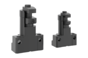
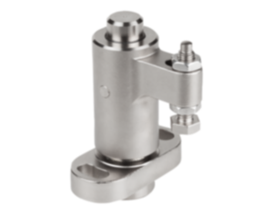
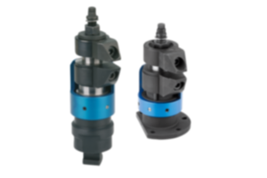
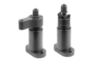
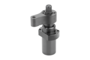
Rotary lever clamps are highly suited for use in cramped conditions. Due to the compactness of the rotary lever clamps, they can be used in a variety of ways in clamping fixtures with little use of space and thus often enable flexible solutions.
Material
Housing aluminium.
Piston steel.
Piston steel.
Version
Piston hardened.
Note
By the rotary lever clamps, the clamping lever is connected to the piston rod. The air supply for the rotary lever clamps is via drilled channels.
The clamping lever moves towards the workpiece with a linear stroke and clamps it. When releasing, the clamping lever retracts so far that the workpiece can be removed vertically. The single stroke of a rotary lever clamp depends on the clamping lever selection.
The clamping elements must be checked regularly for dirt and cleaned if necessary.
When selecting the installation position, it must be ensured that no swarf nests can form in the swivel area of the lever of the rotary lever clamp.
The flange surface of the rotary lever clamp should be adapted to the height of the workpiece during installation and a horizontal positioning of the clamping point should be available.
By positioning the rotary lever clamp correctly, workpiece tolerances can be optimally compensated for despite the short clamping lever.
High forces can be generated with the rotary lever clamps. It must be ensured that the workpieces and clamping fixtures are designed for these loads.
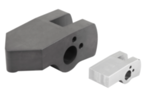
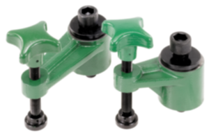
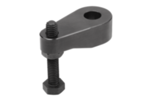
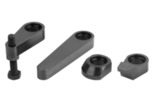
Rotary lever clamps can be fitted with individual tension levers. The clamping force of a rotary lever clamp is dependent on the lever length.
The tension lever for the rotary lever clamp is not supplied.
Follow safety instructions.
Method of operation
Drilled channels.
Technical Data
Max. operating pressure: 6 bar.
Assembly
See mounting contour.
Advantages
- No lateral forces during clamping.
- Low mounting dimensions.
- Wide selection of levers.
- Collision-free accessibility to the workpiece.
- Lineless pressure supply.
- Low mounting dimensions.
- Wide selection of levers.
- Collision-free accessibility to the workpiece.
- Lineless pressure supply.
Scope of delivery
Supplied with 4 DIN EN ISO 4762 cap screws, grade 8.8.
On request
Larger piston diameters, longer strokes and with position control.
Drawing reference
1) Tension lever length (see 04624-30)
2) Travel (see 04624-30)
3) see accessories
4) Mounting contour
5) Rounded edges
6) Loosen
7) Clamping
2) Travel (see 04624-30)
3) see accessories
4) Mounting contour
5) Rounded edges
6) Loosen
7) Clamping
Accessory
Tension levers for rotary lever clamps 04624-30.
Important note on downloading CAD models
In order to download our CAD models, you must log in first. If you have not created an account yet, please register under "My Account" (right side of the screen) and follow the instructions.


