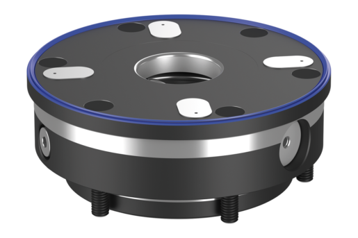


Clamping module
UNILOCK
mild steel
case-hardened and ground
- Automation-compatible
- Turbo function as standard
- Dirt wiper
- Offset support faces with air system control
- Feedback function
1 819,49 €
plus sales tax
norelem.product.details.availability.details.offline
Added to your shopping cart
Designation
Clamping module
Version 1
UNILOCK
Version 2
1447
Body material
mild steel
Body surface finish
case-hardened and ground
P=Operating pressure (bar)
6
B
15
D
138
D1
110
D2
144
D3
12
Form definition
without rotation lock
G
M08
H
55,7
H1
39
H2
18,1
H3
16
H4
7
H5
11,5
L
24
L1
62
Retract. force with turbo (kN)
28
SW
6
Description
Material
Steel.
Version
Contact faces case-hardened and ground.
Note
The UNILOCK clamp modules can be mounted in any position, with or without projection on machine tables or as part of fixtures (plates, cubes, towers etc).
The UNILOCK clamping module ESA 138 is especially suitable for automated clamping fixtures. The integrated feedback function together with the four offset support faces with air system control can ensure process reliability with automated clamping fixtures. Thus, the clamp slider position ”open/closed” and the support control of the clamping pallet can be monitored on the clamping module. The dirt wiper prevents dirt from being deposited on the surface of the clamping module.
The pneumatic control of the clamping modules can be carried out independently or together.thus an individual zero-point clamping system can be fabricated.
The modular design allows the number of and distance between the clamp modules to be ideally adjusted to suit the clamping task. The set-up times are significantly reduced and so the running times of the machines are extended.
The high clamping forces are generated by the integrated spring package (the unit is clamped without constant air pressure).
Clamping is released pneumatically.
Even in the event of a pressure drop or fluctuations in the compressed air supply, the full traction force is maintained.
All clamping modules have a turbo function included as standard. A short air impulse at the ”Turbo” air port increases the normal traction force, achieved by the springs, significantly. Consequently, the clamping modules can also be used for heavy-feed machining.
Use of the turbo function for maximum traction force is recommended.
The following clamping forces are possible with the UNILOCK clamping bolt in conjunction with M10, M12, M16 fastening screws:
- Clamping force (M10) 35,000 N
- Clamping force (M12) 50,000 N
- Clamping force (M16) 75,000 N
Clamping force with DIN EN ISO 4762 -12.9 cap screws
Clamping bolts may only be clamped in conjunction with a mounted interchangeable unit in the clamping module.
A consistent clamping bolt size for all clamping modules and compatibility with the 5-axis module clamping system 80 guarantees diverse combinations of application possibilities.
Technical Data
- Traction force with Turbo from 28 kN.
- System pressure: 6 bar, lubricated air.
- Repeat accuracy ≤ 0.005 mm.
- Temperature range 5° to 60° C.
- Optional port for blow-our air.
- System pressure: 6 bar, lubricated air.
- Repeat accuracy ≤ 0.005 mm.
- Temperature range 5° to 60° C.
- Optional port for blow-our air.
Advantages
- Automation compatible.
- Feedback function for clamp slider position ”open”.
- Feedback function for clamp slider position ”closed”.
- Offset support faces with air system control.
- Dirt wiper.
- Turbo function as standard.
- Repeat accuracy ≤ 0.005 mm.
- Positioning via short taper..
- High traction force.
- Setup time optimisation.
Scope of delivery
- 1x clamping module.
- 2x O-rings Ø9x1.5 for media feed.
- 6x O-rings Ø9x1.5 for feedback function.
- 6x fastening screws.
- 6x cover caps for fastening screws.
- 2x O-rings Ø9x1.5 for media feed.
- 6x O-rings Ø9x1.5 for feedback function.
- 6x fastening screws.
- 6x cover caps for fastening screws.
Attention
Recommended nominal hose size:
- Up to four clamping modules, hose size 6 mm.
- From five clamping modules, hose size 8 mm.
- Up to four clamping modules, hose size 6 mm.
- From five clamping modules, hose size 8 mm.
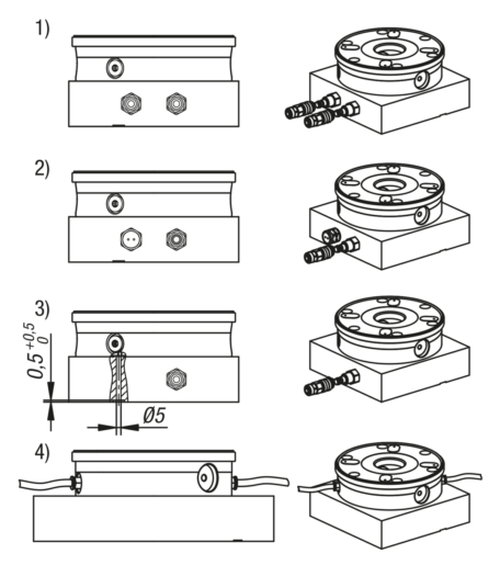
Function principle
The clamping modules can be connected either via the connections on the base plate or directly on the clamping module via the threaded port.
In order to guarantee the function of the clamping slides, the venting of the upper piston chamber must be carried out via the ”Turbo” air port.
For this there are four options:
1) Connection and use of the turbo function in the base plate next to the ”Open” port. This enables the clamping module to be additionally tensioned with a short air pulse if required. (recommended)
2) Simple hole in the baseplate connected to the turbo port to permit air to escape. Do not use a connection with a shut-off function to seal the hole against dirt, instead a venting screw should be used.
3) In the third case, the piston chamber must be vented via a bore that is connected below the baseplate via a transverse slot. This bore must join with the turbo port so that venting can take place.
4) If the clamping module is controlled from the side, the one vent screw must be inserted at this point.
Drawing reference
1) Mounting contour
a) Underside hose-less port (feedback function clamp slider position open)
O-ring Ø9x1.5
b) Underside hose-less port (turbo)
O-ring Ø9x1.5
c) Underside hose-less port (feedback function clamp slider position closed)
O-ring Ø9x1.5
d) Underside hose-less port (system control) O-ring Ø9x1.5
e) Underside hose-less port (open)
O-ring Ø9x1.5
f) Lateral connection G1/8 (turbo)
g) Lateral connection G1/8 (actuator open)
h) Centring rim
i) Vent
Accessory
- UNILOCK clamping pin 42208, 42209, 42208-05, 42208-10.
- UNILOCK protective bolt for clamping module 42796.
- UNILOCK protective bolt for clamping module 42796.
Important note on downloading CAD models
In order to download our CAD models, you must log in first. If you have not created an account yet, please register under "My Account" (right side of the screen) and follow the instructions.
Other customers also bought


