{"product":{"productId":"agid.27437","price":200.49,"name":"SCREW-IN CYLINDER HYDRAULICDOUBLE-ACTING, DK=16, HUB=50, DRILLEDCHANNELS STEEL"},"currency":"EUR"}
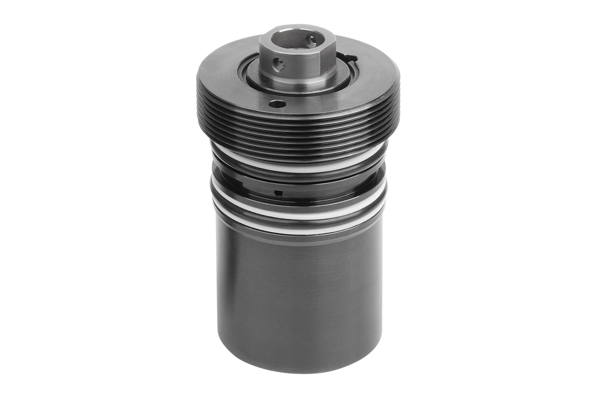


Screw-in cylinder
hydraulic
steel
black oxidised
- Integrated metal wiper
- Low mounting dimensions.
- Housing is fully embedded in clamping fixture
Sales unit
€200.49
plus sales tax
norelem.product.details.availability.details.offline
Added to your shopping cart
Item
Screw-in cylinder
Version 1
hydraulic
Main
material
steel
Surface finish
body
black oxidised
Compressive force
at 100 bar
(kN)
2
Compressive force
at 500 bar
(kN)
10
Connection
type
drilled channels
D
20
D1
22
D2
10
D3
3,5
Form definition
double-acting
G
M30x1,5
G1
M6x15
H
90
H1
84
H2
12
H3
24
H4
45
H5
24
H6
8
H7
38
L
23
Oil requirement /
10mm return stroke
(cm³)
1,22
Oil requirement /
10mm travel
(cm³)
2
Piston Ø
16
SW
8
Tractive force
at 100 bar
(kN)
1,22
Tractive force
at 500 bar
(kN)
6,10
travel
50
Description
Product description
Cyclic-related, linear strokes are possible with the screw-in cylinders with double-acting function. Both travel directions are power actuated with the double-acting screw-in cylinders. Double-acting screw-in cylinders can be used as thrust or traction cylinders. These screw-in cylinders are often used on fixture plates and plates for plastic injection moulding tools.
The integrated metal wiper prevents damage to the piston rod surface by preventing swarf getting into the screw-in cylinder. The protection given by the seal ensures the longevity of the products.
The integrated metal wiper prevents damage to the piston rod surface by preventing swarf getting into the screw-in cylinder. The protection given by the seal ensures the longevity of the products.
Material
Housing and piston steel.
Seal NBR
Seal NBR
Version
Housing black oxidised.
Piston hardened.
Piston hardened.
Note
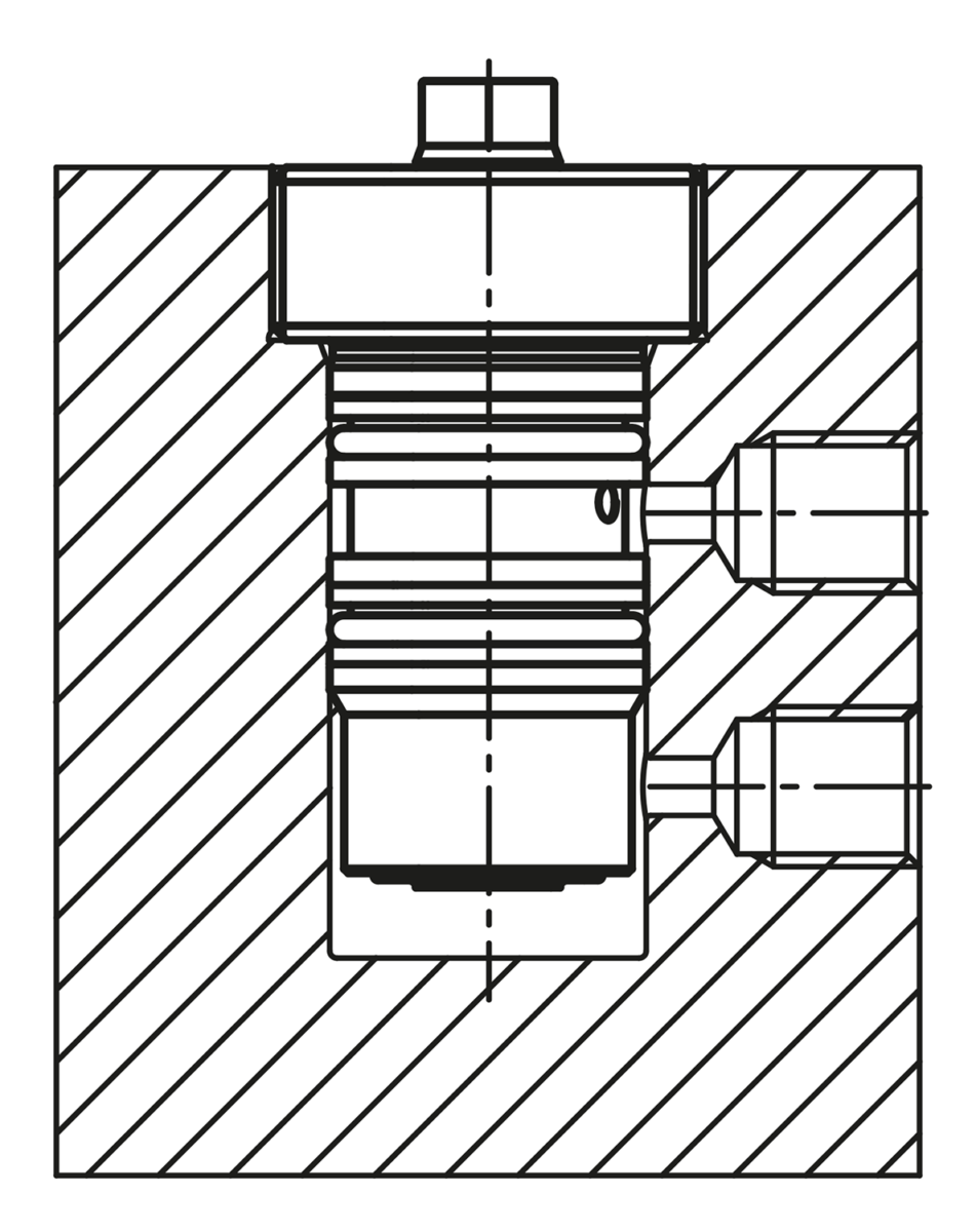
Due to the compact design of these screw-in cylinders, no internal stop for the piston return stroke is installed. It must be ensured that the specified installation depth of the screw-in cylinders is adhered to, as these use the bottom of the mounting hole as a stop for the return stroke.
Care must be taken to ensure that no shavings remain in the drilled holes when producing the drilled channels for the screw-in cylinders. These can damage the seals of the screw-in cylinders, which can lead to leaks in the product.
To avoid damage to the seals during installation, make sure that the lead-in chamfers as well as the transverse holes for the oil supply are well rounded.
Thrust pieces are not supplied.
Follow safety instructions.
Method of operation
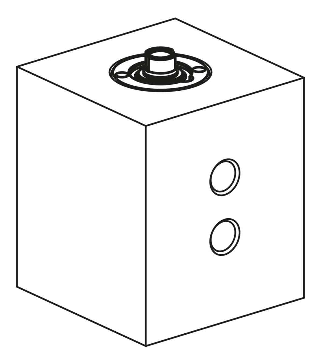
Drilled channels.
Technical Data
Max. operating pressure: 500 bar.
Assembly
See mounting contour.
On request
Larger piston diameters and longer strokes.
Drawing reference
1) Mounting contour
2) Retract zylinder
3) Alternative oil supply, extend cylinder
4) Rounded edges, max. R0.5
2) Retract zylinder
3) Alternative oil supply, extend cylinder
4) Rounded edges, max. R0.5
Accessory
- Rest pads 02153.
- Self-aligning pads 02000, 02080, 02081, 02005, 02006.
- Gripper screws, hexagonal 07114.
- Self-aligning pads 02000, 02080, 02081, 02005, 02006.
- Gripper screws, hexagonal 07114.
Important note on downloading CAD models
In order to download our CAD models, you must log in first. If you have not created an account yet, please register under "My Account" (right side of the screen) and follow the instructions.
Other customers also bought


")


")
")


